Merry Xmas. I had hoped to post details today of a major step forward in this project but Santa was unable to fit my Xmas present on his sleigh... The latest details from Santa's workshop suggests I'll be getting my present some time during the second week in January.
Best wishes for Xmas and the new year.
GD427 in action

Saturday, 25 December 2010
Saturday, 30 October 2010
Just keep chipping away...
No pictures this week, not really much to show. Just grabbed an hour or two in the garage today and finished of the wiring for the other front headlight/indicator. I also drilled the holes through the floor for the seatbelt mounts. This is just a matter of holding the mounting plates in place and using the them as a guide for the drill. I've also completed the electrical connection to the heater and began marking the dashboard ready for cutting out. The heater has three speeds but there's only provision in the GD wiring loom for two so I've connected the fastest and slowest speed terminals. It seems that later dashboards have the locations for the guages pre-marked, mine hasn't but with a bit of hunting around the other blogsites and a bit of help from the guys on the cobra club forums (www.cobraclub.com) I've got all the dimensions I need to mark them out myself.
Saturday, 23 October 2010
Chassis complete
I spoke to Andy at GD last week and my chassis has been built and was being sent away to be powder coated. This next part of the build should see some major progress and it's fair to say this is the quick but expensive part. I'm busy putting together a list of things to be done before the body goes on. If everything goes to plan I aim to collect chassis, engine, gearbox, propshaft, exhaust system and a few other bits on a Friday and by Sunday lunchtime have all this bolted together with the body on... Wishful thinking ? maybe, but working in a single garage with no room to store both body and chassis seperately kinda makes it a necessity, nothing like a bit of pressure to sharpen the mind eh !
Lights wired
I solved my issue with the polevolt connectors, I think others may have mounted these a little differently. I've mounted the p-clips around the collar of the female half of the connector and found the 25mm p-clips I used were too small. This was mainly down to the width of the band which with the ruber lining was too wide and fouled the "clip" part of the connector. I cut a notch into the rubber in these areas which got the band fitting nicely and then used washers to space the p-clips apart so they didn't squash the connector out of shape. The washers allowed me to fine tune the clamping pressure around the connector and with the notches cut out, meant that irrespective, the connector was now trapped and couldn't slide out.
A picture speaks a thousand words...
A notch on the top allows the connector to be trapped by the metal band of the p-clip

The same on the bottom meaning the connector is not only clamped, it physically cannot moved forwards or backwards

By varying the number of washers used a spacers I could vary the clamping pressure of the p-clip ensuring a tight fit but not so tight it squashed the connector, distorting the shape and negating the waterproof seal with the male half.

Fitted into position... The female part is fixed to the body with the male part on the headlight/indicators. When the lights are fitted for the last time (after the body polish), I'll ziptie the wires together and then into a ziptie mount secured to the rear of the headlight bowl.

Sunday, 26 September 2010
Lights
Spent this afternoon wiring up the front headlights and indicators. I've gone for the 4-way waterproof connectors from polevolt in common with others, which provide a really neat solution to connecting everything up but does involve cutting off the existing connections, cutting the wiring to length and crimping on your own spade terminals. What makes it particularly tricky is that most of it has to be done under the wheelarch working with relativley short lengthes of wire. I also took the opportunity to run all the cables through protective sheathing, sealing the ends with heat shrink. This is probably all overkill but it has made a very neat job and I quite enjoyed doing it !

I decided to secure the connectors with p-clips but had some trouble with the sizes. When tightened down, the P-clips (25mm) seemed a little tight and distorted the polevolt connectors, squashing them out of shape and negating the sealing properties and the benefits of them being waterproof. I think it's just a case of cutting the rubber band of the p-clip back a little but for now, they are temporarily mounted until I can sort something out.

I've also finished painting the isoflex liquid rubber under the arches. I've gone for two coats at the moment but may add another at a later date.
Monday, 6 September 2010
Just keep moving forward...
A few pictures just to show where I'm up to. there no major steps forward here, just small jobs being ticked off the list, but as the title suggests I'm trying to keep the momentum and keep moving forward.
Here you can see that both of the wiper spindles have been fitted


Here you can see the relay block and fuse box mounted along with the hot air outlet for the heater and the windscreen support bar which extends across the cockpit behind the dashboard. It all gets a bit tight in this area so I'm glad to have that part out of the way. If you use the Vectra column, before mounting the relay block there is a small modification to the wiring required which I strongly recommend you carry out first.

Here you can see that both of the wiper spindles have been fitted

I've started to paint stonechip under the front arches and in common with a few other builds I've been following I've used Isoflex liquid rubber which is intended as a roofing product but leaves a rubberised coating which should cut down on the spider web type of cracking often caused by stones flying up under the arches from the tyres. This is after the second coat and as you can see is still drying. This has to be the least enjoyable part of the build so far and is arm acheing, sticky, smelly and new T-shirt ruining.... ! (The lights and indicators have been removed for this part of the build and will probably only go back on now once the body has been polished.)

I've also fitted the heater for the last time after buying silicon rubber hose to fit over the outlets. The two outlets are at right angles to each other meaning you need one straight hose for the outlet which exist horizontally and one with a 90 degree bend in it for the outlet which exists vertically. Rather than buy two, I bough one 90 bend hose with extra long legs and simply cut one leg short using the off cut as the straight section for the other. Both of these will need cutting to length so I've left them long for now.
You can also see the battery studs which extend from with the wheel arch cavity containing the heater through into the engine bay to provide convenient power take off.

Here you can see the relay block and fuse box mounted along with the hot air outlet for the heater and the windscreen support bar which extends across the cockpit behind the dashboard. It all gets a bit tight in this area so I'm glad to have that part out of the way. If you use the Vectra column, before mounting the relay block there is a small modification to the wiring required which I strongly recommend you carry out first.

The last photo shows the dashboard temporarily held in place prior to marking out for the guages

Sunday, 25 July 2010
Forward wiring loom started.
Little bit more progress this week. I fitted the side vent on the driver's side so that's both of them done now. I'm going to leave them wrapped in masking until I fit them for the last time. I still have to tidy the recess itself and spray it and the spacing tubes matt black.

I also bought some new polish/compound. Using a rotary polisher and Farecla Profile 200 with a wool pad I polished the bulkhead in the engine bay. This was followed by 500 on a lambswool pad and finally glaze on a polishing foam. Other than the odd shaped head I seem to have developed, I'm very pleased with the results.

With this area finished I could start to install the forward wiring loom. Just got a couple of "p" clips on to hold it in place, the rest will have to be left for another day.

Sunday, 11 July 2010
Bonnet Locks Finished
Quick update.. Cut the slots into the bulkhead to take the bonnet locks and repaired a few scratches with gelcoat. Still need to finish the edge in places but otherwise the bonnet is now finished and just needs polishing. I'm going to leave that for the time being and keep to my plan to trial fit all components and then take them all off again before polishing the body. Once that's finished, the parts can all go back on and be fitted permanently.
Everything seemed to take a long time today and I don't feel I've got much to show for it. One thing I have done this week is order the chassis. I'm also shopping for an engine and gearbox. When that lot arrives there should be some major advancement in a very short space of time. I've gone for the "Euro" option which comes as a rolling chassis with all the suspension components, hubs, drive shafts, diff etc already bolted in place . The plan will be to bolt engine, gearbox, exhaust and a few other bits onto the chassis and then drop the body straight on. I've still got a long list of jobs to finish before hand but I'm really quite excited !
Everything seemed to take a long time today and I don't feel I've got much to show for it. One thing I have done this week is order the chassis. I'm also shopping for an engine and gearbox. When that lot arrives there should be some major advancement in a very short space of time. I've gone for the "Euro" option which comes as a rolling chassis with all the suspension components, hubs, drive shafts, diff etc already bolted in place . The plan will be to bolt engine, gearbox, exhaust and a few other bits onto the chassis and then drop the body straight on. I've still got a long list of jobs to finish before hand but I'm really quite excited !
Sunday, 4 July 2010
Bonnet Locks .....
... or how to fit a square peg in a round hole.

The lock itself is prevented from turning in the hole by have a square neck with rounded off corners. In order to mark out for the square section to be cut I placed the barrel in position and aligned strips of masking tape to the edge of the "flats" to transfer the square onto the bonnet.


I used a 20mm hole saw to cut the holes in the bonnet for the locks to fit into

The lock itself is prevented from turning in the hole by have a square neck with rounded off corners. In order to mark out for the square section to be cut I placed the barrel in position and aligned strips of masking tape to the edge of the "flats" to transfer the square onto the bonnet.

I then used a small file to cut back the edges of the round hole to the edge of the masking tape to create the square hole.

Both locks fitted and the rest of the holes drilled and bolts fitted to the bonnet scoop.

Next job will be to cut the slots in the bulkhead which the bonnet locks slot into.
Sunday, 20 June 2010
Windscreen... second attempt
Spent Father's Day with my Dad, working on the car... doesn't get much better than that!
After my first attempt at rigging up some battens to assist with marking the holes on the screen support legs I went back to the drawing board and built something a little more substantial. This time it worked like a dream and made transferring the fixing holes to the legs childs play. The next part was not quite straighforward as we had terrible trouble drilling the legs themselves. I had thought this part would be relatively easy but despite having a good set of drill bits, a drill press and clamp, the bit was snatching in the material and making a right old mess. Luckily we had started with a small drill as a pilot and were gradually moving up in size so whilst it was a bit worrying and quite honestly frustrating, we hadn't done any damage. We had no option but to down tools and take some time out. Whilst having a cup of tea I turned to the internet and posted a quick message on the Cobra Club Forum asking for some guidance. Within a few moments we had our answer, we were using too slow a drill speed. My thanks to "Toddy" for putting me straight. Unfortunately Dad had to leave so he never got to see the progress I made once I upped the drill speed. Here's a few photos, partly to record my progress for the blog but also to show Dad what I got up to after he left.

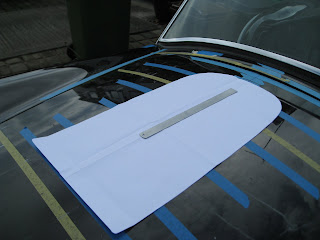
Having got the holes drilled in the windscreen support legs and got the screen mounted, my thoughts turned to the bonnet scoop. I had previously spent some time marking a centre line on the bonnet and after making a paper template of the scoop, cutting it out and folding in half, I aligned the centre of the template with the centre of the bonnet and marked it's outline onto the bonnet in preparation for the scoop itself.

After my first attempt at rigging up some battens to assist with marking the holes on the screen support legs I went back to the drawing board and built something a little more substantial. This time it worked like a dream and made transferring the fixing holes to the legs childs play. The next part was not quite straighforward as we had terrible trouble drilling the legs themselves. I had thought this part would be relatively easy but despite having a good set of drill bits, a drill press and clamp, the bit was snatching in the material and making a right old mess. Luckily we had started with a small drill as a pilot and were gradually moving up in size so whilst it was a bit worrying and quite honestly frustrating, we hadn't done any damage. We had no option but to down tools and take some time out. Whilst having a cup of tea I turned to the internet and posted a quick message on the Cobra Club Forum asking for some guidance. Within a few moments we had our answer, we were using too slow a drill speed. My thanks to "Toddy" for putting me straight. Unfortunately Dad had to leave so he never got to see the progress I made once I upped the drill speed. Here's a few photos, partly to record my progress for the blog but also to show Dad what I got up to after he left.

Having got the holes drilled in the windscreen support legs and got the screen mounted, my thoughts turned to the bonnet scoop. I had previously spent some time marking a centre line on the bonnet and after making a paper template of the scoop, cutting it out and folding in half, I aligned the centre of the template with the centre of the bonnet and marked it's outline onto the bonnet in preparation for the scoop itself.

Time was getting on by now and I wasn't going to get the scoop finished but partly to see what it looked like mounted and partly to keep it somewhere safe where it couldn't get damaged I drilled three of the mounting holes and bolted it on.

Sunday, 13 June 2010
The Windscreen Arrives...
Popped down to GD on Saturday morning to collect my windscreen and bonnet scoop. I wanted to fit the screen so I could get onto fitting the wipers but also so I could fit the windscreen support frame and then the other parts in this area such as forward wiring loom, relays etc.
One thing I hadn't given much thought was where to keep the screen until it was needed, I didn't really want to leave it in the garage, her indoors wasn't keen on it being left in the spare room and to be honest with two little'uns running around neither was I. The only solution left was to fit it ! :-)
I shamelessly copied Simon Rudmans method of making some spacers the same thickness as the frame legs and fixing battens in place to help locate the frame fixing holes and transfer them onto the frame legs. The spacers were made from penny washers wrapped in masking tape.

The battens made from some ply I had to hand and held in place with decorators caulk. Now this isn't the strongest of fixings but it would be very easy to get of and clean up afterwards. The idea here is that once the caulking was dry, I could remove the bolts and the spacers, slide the frame legs into place behind the battens and mark through the holes in the ply to transfer the fixing points onto the frame legs for drilling.

As with most holes the slots in the body were kindly marked by GD in the factory. I masked the area up, made some holes with a drill bit slightly smaller than the width of the slot and then opened it up with a file.


The frame legs were then fixed onto the screen, the whole assembly lowered into place with a support of 930mm used to prop the screen in place. Unfortunately this was as far as I got, partly due to rain stopping play but also becasue the decorators caulk I used the hold the battens in place wasn't as strong as I'd hoped and I knocked them off when passing the frame legs through the slots I'd cut. At least the screen can't (shouldn't) get damaged where it is but there it'll have to stay for now until I get time to attempt a better method for marking the fixing holes in the frame legs.

Couldn't help placing the scoop in place for the final photo

Friday, 11 June 2010
Doors take 2
The first time I fitted the doors it was just really to make a start, since then they got in the way a few times and were taken off again. Many of the small jobs have now been completed and I've spent some time cleaning up the door edges and polishing the undersides ready for final fitting. There's still some work to be done but I thought I'd put them back on again and this time spend some time getting them lined up correctly. I've had to enlarge the holes in the back edge to adjust the position of the catch and open up the holes for the hinge arms but with a bit of fettling I've got this one at least fitting pretty well. It even bounces of the sprung catch when pushing it gently to !


Side Vents
I fitted the first of the side vents last night. The vent itself is stainless steel and is pictured here still covered in masking tape to prevent it getting scratched. It was slightly oversize for the recess and needed the corners reshaping slightly for it to sit comfortably inside. It is fixed with M3 x 30mm button heads that are self tapped into 2.5mm holes drilled in the body within the recess. In order to space the vent off the inside surface of the recess and control the depth that it sits inside, I've used some aluminium sleeve on the backside of the bolts as spacers which I bought from B&Q. I cut them to 18mm which seems to be about right. Before the vent is fitted for the last time I'll spray the spacers and the recess matt black.


Sunday, 30 May 2010
Tidying up a few edges
No pictures, just a quick description of what I've been up to other than trampolining.
Most of the components fitted to the body are trial fitted but I'm getting towards the stage where I'm happy with the fit and they can be permantly bolted into place. Thoughts have turned towards polishing the body and making good any and areas which might require a little attention. This week I've been concentrating on the bonnet and going all around the edge, rubbing down, filling with gelcoat and rubbing again to get a nice clean finish. Once that's done, there's some work to do on the edge of the boot lid and along the top of the doors. Most things have now been fitted at one stage or another, the only major part left to tackle is the windscreen which I've yet to purchase and is the next part of the jigsaw allowing the wipers/wiper motor to be fitted. I'll probably trial fit like most of the other stuff to make sure I'm happy and then it's an all over body polish and this stuff can all be bolted back on for the last time.
Most of the components fitted to the body are trial fitted but I'm getting towards the stage where I'm happy with the fit and they can be permantly bolted into place. Thoughts have turned towards polishing the body and making good any and areas which might require a little attention. This week I've been concentrating on the bonnet and going all around the edge, rubbing down, filling with gelcoat and rubbing again to get a nice clean finish. Once that's done, there's some work to do on the edge of the boot lid and along the top of the doors. Most things have now been fitted at one stage or another, the only major part left to tackle is the windscreen which I've yet to purchase and is the next part of the jigsaw allowing the wipers/wiper motor to be fitted. I'll probably trial fit like most of the other stuff to make sure I'm happy and then it's an all over body polish and this stuff can all be bolted back on for the last time.
Wednesday, 12 May 2010
Bit of fun...
As well as finishing off a few loose ends around the body today, I built this... supposedly for the kids but I want first go !


Tidying up..
Had another good day today, not much to show for it but basically went round and tidied up a few loose ends. Finished the extended footwell, polished the engine bay in readiness to fit the forward wiring loom and finished off a few rough edges underneath that were left over from when the body was in the mould.


Tuesday, 11 May 2010
Pedal Box & Extended Footwell
Managed to get a bit more done today namely fitting the pedal box and the extended footwell. I actually made the cut for the extended footwell some time ago and all I really did today was drill the mounting holes and fit the jacknuts to hold it in place. It still needs a little fettling to get everything lined up and them some additional bodywork cut away to open the hole up as I deliberately cut it too small to start with. You can always make a small hole bigger...


I started the pedal box by removing the pedals and roughly positioning the frame to get an idea where it should go. The frame is mounted as far left as possible leaving enough room to fit the carpet alongside. The top of the frame sits roughly 5mm below the curved ledge that is the horizontal corner section in the engine bay. By marking and drilling the centre hole first, you can temporarily fit the frame in place which makes it much easier to mark the other holes. 


I started the pedal box by removing the pedals and roughly positioning the frame to get an idea where it should go. The frame is mounted as far left as possible leaving enough room to fit the carpet alongside. The top of the frame sits roughly 5mm below the curved ledge that is the horizontal corner section in the engine bay. By marking and drilling the centre hole first, you can temporarily fit the frame in place which makes it much easier to mark the other holes.


Access Panels to Footwell Compartments
With hindsight, I'm probably better using standard M5 bolts than button heads to secure the access panels. With all the rubbish thrown up under the wheel arches once on the road, bolts with a standard hex head will be a lot easier to remove using a socket/spanner than button heads with an Allen key. I'll add some bolts to my shopping list and change them over at a later date.
I've also chosen to secure the panels at the corners, it's crossed my mind whether these would have been better secured half way along the edges to pull the panel tighter against the bulkhead, I guess time will tell...
I've also chosen to secure the panels at the corners, it's crossed my mind whether these would have been better secured half way along the edges to pull the panel tighter against the bulkhead, I guess time will tell...
Monday, 10 May 2010
A Step Closer...
A bit more progress made, no big write up, all fairly self explanatory
Front lights & Indicators fitted


Rear wiring loom fitted


Access panels fitted to footwell compartments. These were backed with strips of 2mm neoprene and fitted with M5 button heads into jacknuts.


Front lights & Indicators fitted


Rear wiring loom fitted


Access panels fitted to footwell compartments. These were backed with strips of 2mm neoprene and fitted with M5 button heads into jacknuts.


The grey strip you can see on the outside edge of the wheel arches is a piece of foam pipe lagging that I've used to protect the edges when I'm pushing the body in and out of the garage.
Monday, 12 April 2010
Fitting The Bonnet
After a long break from the garage, (I think I may be a "fair weather" builder !) I found some time over the weekend to pick up the tools and make some more progress on the build. My last major accomplishment was fitting the bootlid and with the same approach in mind I set about fitting the bonnet.

Using small strips of card I "gapped" the bonnet by sitting it in the opening and wedging pieces of card along the sides to centralise it. Once centred I measured the drop in height between the bonnet and the surround and made some spacers, again out of pieces of card to sit in the aperture and raise the bonnet to the correct height. After a few last minute tweeks I attached the bonnet hinges to the body through the radiator opening and swung the hinges up to meet the underside of the bonnet to gauge how much fettling would be required to get them to fit. Unfortunately, quite a bit... I decided that the best approach would be to re-weld the hinge plates to the arms and set about cutting them off.

Once removed I fitted the plates to the bonnet and the hinge arms to the body, I then swung the arms up to meet the plates and held them in place with a few tack welds. Once it had cooled down, I removed the hinge, made a permanent job of the welds on the bench and re-fitted.

Voila, perfectly fitted hinges with a perfectly centred and height adjusted bonnet

Subscribe to:
Posts (Atom)