GD427 in action

GD427 in action

Saturday, 7 November 2009

Boot Lid Pictures

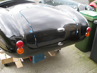
I spent a fair bit of time positioning this catch in the middle of the boot opening only to find it didn't line up with the locking mechanism and handle which was positioned in the middle of the boot lid. I guess I was expecting too much, alternatively, I didn't think it through properly.... you choose. As it's more important for the handle to be in the centre of the boot lid I had to move the catch across a little to line up.


The boot lid was positioned by packing the opening with card held down by masking tape to bring it up to the correct height and to hold it central. In this way I could remove and replace the boot lid to my hearts content knowing that it went back in the same position each time.


With some help from my Dad... hey Dad, you're on the internet !... I climbed into the boot and had my Dad replace the bootlid behind me. I could then bolt the hinges into place and offer up the boot catch to mark it's position before fixing.


Here's the catch after fitting the T-Handle on the outside of the boot lid. The square section will be cut to length later.


I also took the opportunity to fit the rear lights, indicators and number plate light. Another step closer and looking a bit more like a car.

Sunday, 25 October 2009

Fitting the boot lid

Camera's playing up at the moment so I can't upload any pictures but I'll update this post as soon as normal service resumes. I've not posted for a while, I have been making some progress but since the small issue with the petrol filler, I've been a little more cautious. In addition, I've decided at the ripe old age of 41 to get me some "ejucation" and I've picked up the text book once more to work towards a professional qualification in Insurance and as my employer has a nice little bonus scheme for passing these exams I thought I'd give it a go.
The latest job to be completed on the car was fitting the bootlid which is held in place by two hinges on the front edge and the lock at the back. The bootlid needs aligned to be central in the boot aperture both front to back and side to side. In addition it's height needs to be the same or at least as close as possible to the surrounding body work. The standard method involves a lot of trial and error and either bending or packing the hinges to achieve the desired result. In order to find out just how much faffing about I was in for I decided to fit the lid in the correct position, held in place by card and masking tape to see how far out the hinges would be. I packed the edge of the aperture with thin strips of card to raise the lid to the correct height and then wedged card into the shut lines to hold it central. Once I was happy, I taped all the card into place, fitted the hinges to the body and with my Dad's help, climbed into the boot and closed the lid behind me. I could then lift the hinges into place against the inside of the bootlid to see how much work was needed to get a good fit. Happily, the hinge plates fitted flush against the underside of the lid showing that just a few of the holes needed enlarging for it all to line up and bolt into place. Nice!
The next job was to fit the catch which is fitted or at least marked for fitment from inside the boot. I'd previously spent a good while positioning the striker plate in the exact centre of the aperture before fixing into place. I fitted the catch to align with the striker plate but it wasn't until I came to fit the handle to the outside of boot lid that I realised that the critical measurement was the handle in the centre of the lid rather than the catch/striker in the centre of the aperture and mine was a little out. I managed to "save" it but there's a good tip for anyone else contemplating the same job. I'll try and post a few pictures to illustrate but I've now fitted the bootlid, fitted the boot handle and lock, the number plate light and the rear lights and indicators. A couple of small jobs in the great scheme of things but the back end now looks like a car which gives a very satisfying feeling. Oh whilst I think of it, another small tip for you, the hole cut for the fuel filler makes a handy hole to feed a lead light through so you can have some light and see what you're doing when you climb into the boot.

Friday, 25 September 2009

Fuel Filler Cap

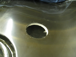
GD had very kindly, clearly marked onto the body the position and exact size of the hole needed to mount the fuel filler. I then, very clearly, drilled the hole too big. Entirely my fault, working late into the evening, getting a bit carried away and just used the wrong size hole saw. Used a 76mm hole saw when I should have used a 64mm.


Now, you can always make a small hole bigger but making a big hole smaller poses a few issues. I guess there a few ways I could've tackled this, I understand there is a filler cap with a larger flange which would've covered the mistake but it looked a bit ugly to me and cost about £80. I could've made a collar to fit inside the hole and reduce the inside diameter but how would I fix it in place. An additional challenge faced me in that when I measured the fuel filler in the hole, the fixing bolt holes were directly in line with any repair I attempted to make meaning that whatever solution I chose it had to be strong and solidly fixed to the body. In the end I chose to re-affix the part I had drilled out which was still lodged inside the holesaw after I abandoned it in digust onto the workbench. Luckily there were enough marks left on it from the original masking tape that I could use as a guide to position the piece precisely where it had come from. I then used additional masking tape and drew some guideline upon it to ensure I had it positioned correctly before suspending the part in it's orginal position using a couple of battens and using a fibreglass kit to place a strip either side and glass the piece back into position from the underside.


Once the initial repair was dry, I removed the batten, placed a strip of fibreglass in the middle and then two extra pieces which covered the whole area.

I then filled the hole which was left by the original holesaw cut with some fibreglass filler before cutting back with the trusty Dremmel and filling with gelcoat and sanding back with wet n dry.


I was quite pleased with the end result and whilst perhaps not as good as it could have been, it was far better than it needed to be considering it would all be covered by the flange on the fuel filler anyway. The hole was drilled once more, this time with the correct size holesaw and finally, as a belt and braces job, I made a plate from 2mm aluminium to fit on the underside of the body for the fixing bolts to pass through and strengthen the whole thing up, effectively clamping the repair between the plate and the filler itself. I will need to get some longer bolts to pass through the extra thickness of the body.
Whilst I would never have chosen to follow this path, I did quite enjoy myself and learnt a little about fibreglassing along the way.... can you tell I'm still trying to put a brave face on....sob, sob !

A new section

Not posted for a little while. A few reasons, been busy working on the house, been busy at work, been ill with the worst bought of flu imagineable (for me anyway) and the recent work completed on the car hasn't really gone to plan....hence a new section to the site.... cock ups. Hopefully thee won't be too many posts :-)

Monday, 8 June 2009

Fitting the Heater - 20:20 hindsight

With a bit of hindsight (there might be a few of these) a better way of fitting the heater would be to make a template of the heater face before drilling any holes and perhaps include an outline of the outside edge, place the template into position on the footwell side and then decide where you'd like the holes to be. Mark these on the template and then transfer these onto the heater face as marks where to drill the holes. Within reason and obviously taking care to avoid the heater matrix, the bolts should then be in a perfect position to enable easy fitment.

Saturday, 6 June 2009

Spit and polish

This is a picture of the rear left quarter when I initially started rubbing down the flashlines. Since then I had quite a bit of practice ! and I've also treated myself to an electric DA polishing machine so I thought I go back and see what I could achieve with a bit more experience under the belt and the means to finish the panel to a high standard.

Firstly I rubbed down the whole panel with 600 grit wet n dry in a horizontal plane, keeping the panel wet at all times. Next I used 1200 grit in a vertical plane, the idea here being that if any horizontal scratches are still showing after this process, they are from the 600 grit and you've still got more work to do. Next was 2000 grit horizontal again with the same idea in mind i.e. any vertical scratches are from the 1200 and you need to keep going. I used a microfibre cloth to dry the panel down and a very bright light in order to see any scratches left between grades.
After the 2000 grit I used Farecla G6 with the polishing machine again keeping the panel wet at all times. After G6 I used G3 which is a bit finer and after that some polish I had previously used on my other car called Menzerna Final Polish PO85RD. I believe the Farecla equivalent is G10. For a really excellent guide to using a DA polishing machine, head over to the Detailing World website and have a read of this:-http://www.detailingworld.co.uk/forum/images/misc/dapolishing.pdf it's aimed at "correcting" paint finish but the basic principles are the same.

Not bad eh!

Installing the Heater

I've been lucky enough to read a how a few other people have installed thier heaters so I've just basically copied what they did, no point in re-inventing the wheel as they say !
This is the heater, the difficulty in mounting this into the wheel arch cavity is that the mounting flanges on each side are very difficult to reach when it's in position. I understand this is even worse in the MKIV body shape which I have here. Standard fitting involves using self tapping screws to hold this in but I really can't see how you manage to get your hand in to tighten them up. So here follows the alternative tried and tested method of fiting the heater.

Firstly remove the flanges, this job was completed using a cut off wheel in the dremel. In truth it's only one side that causes the problem but the alternative solution is so neat I decided to apply it to both sides. Here you can see the flanges on the end caps which have been removed first to make the job easier

Heater temporarily reassembled to show how it looks with the flanges removed

Next, dril four holes into the face of the heater, after you removed the innards to prevent any damage, and fit four Rivnuts.

Make sure that the position of the rivnuts does not interfere with the heater matix. My holes for the lower rivnuts were drilled in line with the holes for the self tapping screws holding the heater outlet plate on.

Make a template of the heater face, carefully marking the position of the rivnuts.

Transfer this to the body by holding the template inplace with the heater outlet which is conveniently removeable from the heater body and then drill four holes to correspond with the position of the Rivnuts. I found this easier from the wheel arch cavity side.

Refit the outlet plate, bolt through from the other side and voila! Heater installed.

View from the footwell.

You can see in this picture that the top left bolt hole is a little close to the outer wall of the footwell and with the washers I was using it wouldn't fit. Not the end of the world I'll just have to use a smaller washer on this bolt. This basically occurs because the passenger footwell has a double skin injected with foam as a safety measure which isn't obvious (unless you think about it!) when looking back from the wheel arch cavity the other side which only has a single skin. See picture above. For reference, my holes were drilled in the heater face 20mm in from the outer edge. I'd suggest it ought to be about 30mm, at least for the top left fixing looking at the face to give you more room to insert the bolts.