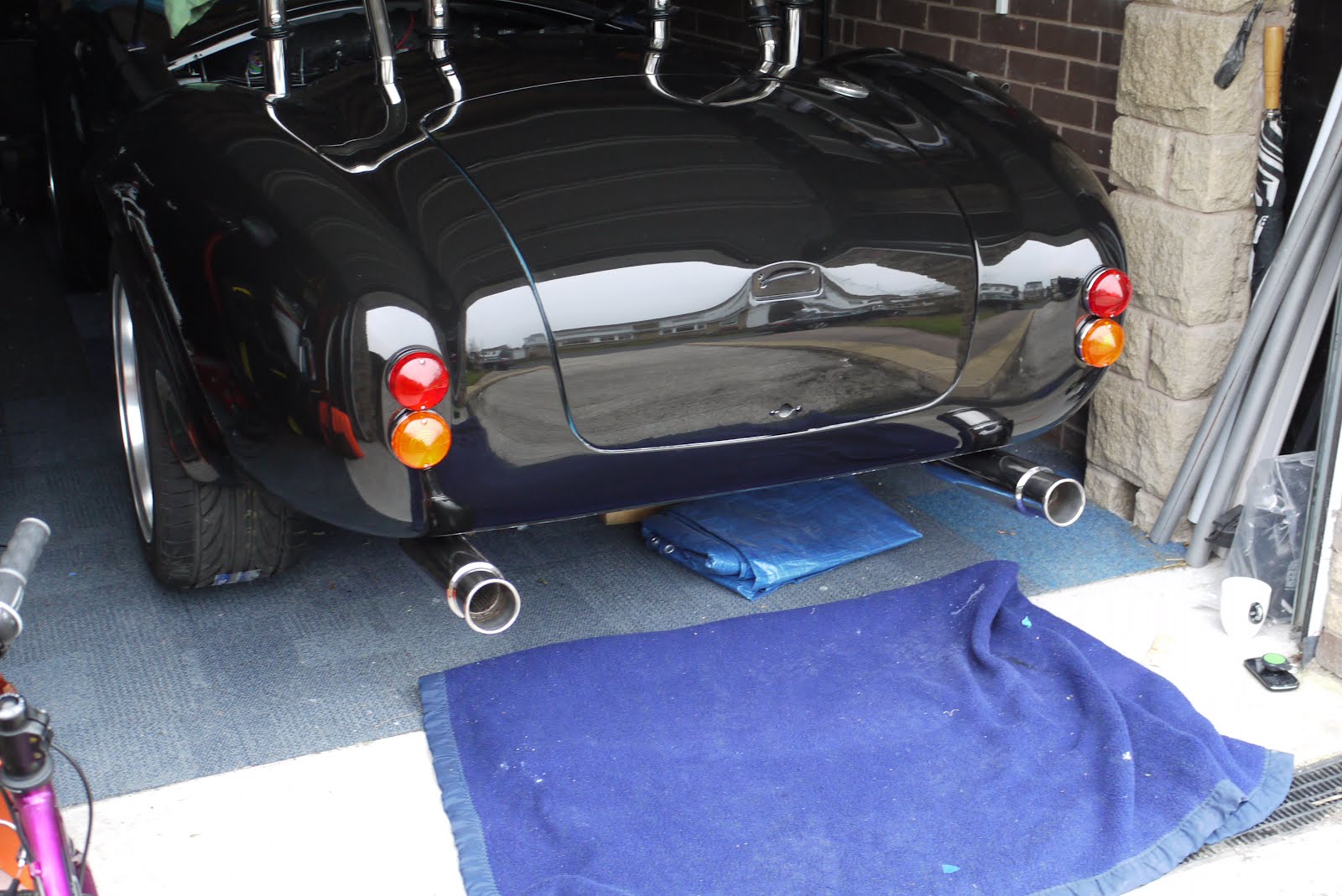
GD427 in action

GD427 in action
Showing posts with label Body. Show all posts

Sunday, 16 June 2013

Badges

I had hoped to go to the Kit Car show at Newark today but the weather wasn't brilliant and as I still haven't got a roof for my car or a tonneau cover, I didn't want to risk it. I took the opportunity instead to tick another small job off the list and fit the badges that Andy kindly gave me when I went for my suspension set up.

These are simply held in place by double sided tape, sometimes called number plate tape. Basically the same stuff you buy in patches to stick your number plates on but this comes on a roll.

The badges themselves are laser cut stainless steel.


Sunday, 5 May 2013

Tis the season

Well the warm weather finally arrived and along with it, 6 months road tax, it seems a long time since I was last on the road. Most of last year was spent building and it wasn't until fairly late in the summer the car was IVA'd and I could start driving it. Consequently I still have a small list of jobs to do...!
With the rush to get on the road I never really paid much attention to mounting the number plates. They have both been mounted with the double sided sticky pads you get from the plate makers and whilst the front one has been OK, with the curvature of the boot lid the rear one kept coming unstuck. So, taking a little inspiration from someone else's work, I made a bracket. This fits underneath and is held in place by the rear number plate light and by using a few rivnuts, allows the number plate to be screwed to it. This was only meant to a mock up in aluminium to see if it would work but it fits so well I may just leave it as is. If I ever run out of things to do I may revisit this and make another one from stainless.


Ta daa... !

Sunday, 8 July 2012

Number Plate

In order to mount a number plate to the number plate bar I made a MDF blank which fits onto the bar using 19mm p-clips. They were a little loose so I used a bit of insulating tape around the bar to pad it out a little. Whilst I haven't got a number plate yet, this area is part of the IVA test and if nothing was fitted in this area it would be fail.

This gave me a chance to get some of my power tools out that haven't been used in while and I used a router to put a nice radius on the edge of the MDF.


Saturday, 5 May 2012

Into the daylight

No real progress today, spent most of it catching up on some DIY but it did give me a chance to get the car down off it's axle stands where it's been since last October, partly to stop any problems arising with the tyres sat in one place over winter but also to give me some access underneath.

It's the first time it's been outside for 6 months and I've not had a chance to really see the effect of all the small changes I've made during this time. Was nice to see it all coming together so I took a few pictures for the record.


Saturday, 14 April 2012

Improvements already...

Ever since I fitted the main engine loom through the dash I'd never been entirely comfortable that the only thing holding it central was the rubber gasket I'd used to to close the hole. Seeing what Martin, another builder had done, inspired me to make some improvements. Firstly I mocked something up in paper which was formed along similar lines to the original stainless ring I had in place but rather than cut the centre out, I planned to make a partial cut and bend the centre forward making a tab to secure the wiring to. Once I was happy, I bought a small sheet of stainless and transferred the dimensions onto some masking tape stuck on the back.


I started by drilling all the holes before making the cuts with a metal blade in my jigsaw. Taking it nice a slowly I gradually cut along all the lines before bending the centre "tab" forwards, putting a small curve into it and tidying up all the edges.


Then it was just a case of removing the original backing ring behind the bulkhead and replacing it with the new one. The oval holes I cut into the tab allows a ziptie to be passed through and secure the loom nice and tight. The gap at the top of the new ring allows it to be placed around the loom rather than having to pass the loom through it.


Worked perfectly, whilst there are no sharp edges I will probably go back at some point and spend a bit of time really rounding them off just in case.

Sunday, 8 April 2012

Bonnet locks & scoop bolts

Finished today by refitting the bonnet locks and the stainless button heads which hold the hood scoop on. The number of bolts is obviously just for show and replicates the rivet pattern found on the aluminium panels of the original cars from the sixties.

Number plate light

As with most things now, this has been previously fitted and then removed for safe keeping. I did need to make some small adjustments as it sat a little high. All it needed was a few holes elongating.


I also completed the wiring inside the boot. I'd previously feed a length of wire through the boot skin for the light which exits through the left hand side hinge arm. To make it easy to remove the boot in future I joined the boot wiring to the loom with a connector which I held in place with a p-clip bent to shape.


Just the rear lights, indicators and fog/reverse lights to connect inside the boot and the rear of the car is complete.

Thursday, 5 April 2012

Front Under Tray

The other job for today was fitting the front under tray. This bolts into the bottom of the nose area, tying the inner wings together. This is also used in some builds to mount the oil cooler but with the engine I'm using this is something that's not deemed necessary as the aluminium block dissipates heat quite nicely on it's own. Gotta say an oil cooler does look "cool" if you'll pardon the pun. I'm lead to believe the under tray also brings some aerodynamic benefits too !


Simply a case of drilling and then bolting this in. The rear of the tray slips between the radiator and it's bottom mount which helps keep it all held firm.

Rear Over-riders

Today was the turn of the rear over-riders. These simply bolt through the rear of the body work and are bolted up from inside the boot. I've been in a bit of a dilemma recently knowing whether to mount things such as the fog and reverse stand-offs and now the over-riders, level, or by eye, trying to keep things looking "right" even if they actually weren't. After a few trial runs using spirit levels, laser levels and various pieces of wood in order to find "level" and use that as a reference point, I gave up and decided that I'd make it look right in comparison to the rest of the car. To that end I suspended a piece of cotton taught between the lens fixing bolts in the rear lights and used that as a reference point to mount the over-riders level compared with the rear lights. As it stands, a spirit level across the rear lights shows them to be pretty close but as I've said before I've no idea whether the floor is level in this part of the garage. Once it's back down off axle stands, if it looks wrong I can always tweak it later.


The first one took a while before I had confidence to wield the drill but once I'd got one side fitted, it was just a case of the same again on the other side using the cotton line as a reference for height and distance from the boot edge as a reference for how far to mount to the side.


I took the lead from Steve and made some angled spacers to fit over the bolts inside the boot to allow the nuts to tighten up squarely in spite of the angle of the bodywork. I've used standard nuts for now but will change these to nylocs once I know they won't be coming off again.

Wednesday, 4 April 2012

Number plate bar

Today's job was the number plate bar. This fits across the opening in the nose and whilst used to mount the number plate, it also serves to fill this space and keep Mr IVA happy as without this, it's an IVA fail. The bar is made of stainless steel and simply bolts onto the inner wings via a L shape bracket on either side. I also have an "under tray" to bolt in which closes this area from beneath and stiffens the whole thing up.

First, I clamped the bar into position to gauge it's height in the opening and how far it should be set back from the nose. I used masking tape to mark a horizontal line for comparison but in the end just used the radiator core behind it for reference.


Once I was happy it was level (with the radiator as least) I drilled the holes and bolted it in. Finding what's level has always been a challenge with this build as I've not checked my floor is level and even if it was, I'm not convinced a fibreglass body shell would be exactly level or even symmetrical. That said, I haven't found anything that's concerned me and reading what people have faced with other manufacturers, I've been extremely pleased. I did need to space the bar off the inner wings just a little with some washers. I'm not sure whether it's supposed to be a little short to pull the inner wings in or to allow for the mounting brackets of the front over-riders where fitted. In any case, it's set where I want it and I can always remove the washers (two each side) or change the mounting points slightly if I need to at a later date.

Monday, 2 April 2012

Fog & Reverse Lights Fitted

New bolts arrived in the post this morning, only a 5 minute job to refit so thought it rude not too ! I used M5 x 50mm button heads. The bolts are long enough inside the boot to make some angled spacers to allow for the curvature of the body in this area. I haven't done this yet, maybe a job for another day as they tighten up quite securely so I'm not sure the spacers are really needed.

Sunday, 1 April 2012

Headlights

A day of easy wins today. Most of the parts I fitted have been on the car before and were removed for storage until the build neared completion, Well that day is coming and it was the turn of the front headlights and indicators. Because I knew I'd be taking these off and refitting later I'd used stainless M5 button heads rather than the self tappers supplied in case fitting, removing and refitting weakened the self tapping threads. Just a case of bolting these in and plugging into the existing waterproof connectors I'd wired in previously.

View from the front


..and from the back


Feeling quite pleased with myself :-)

Scoop

I'd temporarily fitted the scoop before but this time it's for keeps. Because the engine I'm using doesn't need airflow to the top of the engine as the intake is located in the nose, the scoop is purely for looks. Rather than cut out the front of the scoop unnecessarily, I've painted it matt black and covered it with stainless mesh. The mesh was cut to shape and left a little long so it tucked under the bottom front edge and could be secured behind. Hopefully the pictures will make it clear. Around the top, the mesh is held in place by tucking into a piece of rubber channel which I glued into place with araldite.


Once the glue had dried, I fitted the top edge of the wire mesh into the channel and used polyurethane adhesive, tiger seal, to stick the mesh which overlapped and tucked under the front of the scoop onto the rear of the scoop face. The scoop then bolts to the bonnet with some stainless M4 button heads.

Windscreen refitted

The windscreen is now back on for good and I've fitted the escutcheon plates around the bottom of the screen legs and those for the windscreen demist vents. The plates around the bottom of the screen were bent slightly to match the curvature of the body in this area and the holes through the body and the underside of the plates sealed with clear silicone. I've also fitted the demister "funnels" (?) which fit under the vents and direct the air onto the windscreen. These are held with the same bolts which secure the escutcheons so the two are done together. A little tip for anyone approaching this stage, I had trouble getting the bolts to screw into the threaded bolt holes in the "funnels". This was due to a layer of paint which had built up so I ran an M5 tap through them to clear them out which made the job so much easier.

Fog & Reverse Stand-offs

After going great guns fitting the fog and reverse stand-offs, the bolts I'd bought were too short. I've ordered some more so should be able to get these mounted in the next couple of days. I've also fitted the rubber seal for the boot which you can see in this picture. Felt good to finally get rid of that blue masking tape. It must have been there for about 3 years now !


...and the striker plate for the boot catch. This has been fitted before but it should be on for good now. Boot shuts nicely and just squeezes up against the rubber as the catch clicks into place.

Wednesday, 28 March 2012

Fog & Reverse Lights

Made a start on fitting the rear fog and reverse lights.
GD supply the mounting bracket which is basically a short length of stainless tube with a plate welded on the end for the light to mount onto. The other end has been profiled to fit the body shape in this area. It took me a little bit of trial and error to get them positioned both centrally and level but I think I'm about there. Next step is to drill some holes and modify the lights themselves by replacing the standard fixing bolts which come affixed to the light with some longer bolts which pass through the light fitting, through the mounting and through the body holding it all together by sandwiching the mounting between light and bodywork.

Monday, 12 March 2012

Exhaust

Spent some time over the weekend doing a little compounding and polishing on the rear deck and boot lid and fitting the rear cherry bombs to the exhaust. The polishing was in preparation for fitting the roll bars for the last time. After all the experimenting I've done with different compounds, polishes and pads my final weapons of choice are:

  • 2000 grit wet and dry by hand
  • Farecla G3 liquid on an Farecla Advanced G-Mop compounding foam by rotary polisher
  • 3M Ultrafina SE on a 3M perfect-it 3 high gloss polishing pad by rotary polisher

I'm getting pretty confident with the polishing now so will probably press ahead and get it looking respectable and on the road and worry about some of the fine detail later otherwise I could spend forever getting it all perfect. It's all going to get scratched and chipped once it's on the road anyway.

Starting to come together now ... !


Sunday, 12 February 2012

Getting sidetracked

This is one of the reasons why this build is taking so long. With all the nice shiny bits under the bonnet, a plain old aluminium mounting bracket for the brake fluid reservoir just wasn't going to do !

Original on the left, mirror polished stainless steel one on the right.


It was made up from some stainless I bought off ebay, bent in a vice, drilled and then polished up a little.


I think deep down inside, there's a part of me that doesn't want this build to end, I keep finding things to change or improve on before it's even on the road. I'll tell you what though, the part of me that wants to drive this thing is getting pi55ed off with it !

Anyway, enough self analysis and on with the build.

Sunday, 5 February 2012

Closure....

Ahhh, remember this..Fuel filler cap.. well I'm finally back round to the filler cap and I'm pleased to say it fits perfectly and you can't see the join. :-)


Once the tank is fixed I can join the two pieces up with some filler hose and finally tick this item off the list.


I've got a little more work to do on the cap itself, it needed a vent installing which involved drilling a hole in the side of the neck, tapping it with a 1/8 NPTF bit and screwing in a fitting which will allow me to install a length of copper tube (brake pipe) to act as a vent. The pipe run will initially rise inside the boot to stop fuel flowing down the vent pipe and then follow a path down and out through the floor of the boot. In theory, with the end of the vent pipe lower than the tank, this should stop fuel running out of the tank through the vent pipe if I'm ever unlucky enough to find myself upside down... scary thought and probably the least of my worries ! Incidentally, the 1/8 NPTF bit wasn't something I had in my toolbox and after a bit of online searching I was a little dismayed at the cost of buying one for a "one off" job. Ebay came to the rescue and I bought one from China for about £8 delivered !

Sunday, 22 January 2012

Boot Wiring

No Pictures today but I've just finished rubbing down and polishing the edges of the boot. I'd had a few goes at touching up the gel coat along the edges where the two skins meet but I seemed to be continuously finding new bits which I presumably missed the last time around. Taking no prisoners I masked up the front and rear face of the boot and using an artists brush painted two thick coats of gel all the way round the edge. It's taken some rubbing down to get the profile back and everything looking smooth but its made such a nice job I wish I'd been a little bolder in the first place.

I've also passed the wiring through the hinge and the boot skin for the number plate light, a little fiddly but I got there in the end.

I'll post some pictures next time.