GD427 in action

GD427 in action
Showing posts with label Heater. Show all posts

Thursday, 28 June 2012

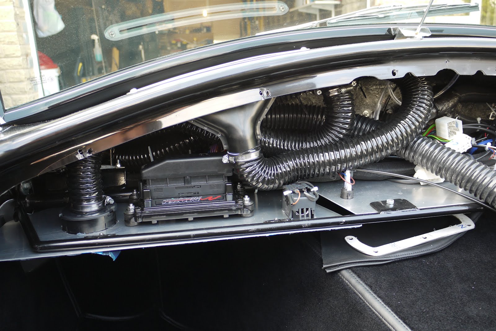
Heater hoses

Started on the heater hoses, this all seems like quite a tight fit, one reason is that the aluminium plates which fit under the dash have to go on last so all of the wiring and heater hoses have to be long enough to attach to the plates before they are pushed up into position.


Each hose, one for each side of the car, splits into two runs, one goes to the footwell and the other to the screen demist vent.


The splitter piece was made from a piece of plastic waste pipe, cut, stuck together and painted black.


Thursday, 11 August 2011

Getting there

Here's a picture of the engine bay after I got rid of all the engine harness, fuse box, ecu connector etc. and shoved it all though the bulkhead into the area behind the dash. I still need to fit the air intake onto the front of the engine where you can see "LS3" written on the black cap.


I've also opted for a bit of bling and fitted these stainless steel pipes rather than lengths of silicone hose which take the hot water from the engine and feed the heater which is hidden under the nearside wing.

Sunday, 13 February 2011

Screen demist pipes

Weather was rubbish today so spent some time inside putting some waste pipe together for the screen demisters. These pipes which I made into "T" pieces, take the warm air from the heater and split this to the screen demisters and the footwell, one for each side. The "T" pieces are joined to the various components by flexible tubing. I found a website which allowed me to print some templates for joining two pieces of pipe together.

It was actually designed for much more complicated joins that I was attempting i.e different sizes, angles, offset etc. but very handy nonetheless.
After cutting out the template and marking the pipe accordingly, I made the cuts and glued them together. Once dry, I'll rub down the joints a little and paint them black...... don't know why, you'll never see them but it just seems like the right thing to do :-)

Saturday, 30 October 2010

Just keep chipping away...

No pictures this week, not really much to show. Just grabbed an hour or two in the garage today and finished of the wiring for the other front headlight/indicator. I also drilled the holes through the floor for the seatbelt mounts. This is just a matter of holding the mounting plates in place and using the them as a guide for the drill. I've also completed the electrical connection to the heater and began marking the dashboard ready for cutting out. The heater has three speeds but there's only provision in the GD wiring loom for two so I've connected the fastest and slowest speed terminals. It seems that later dashboards have the locations for the guages pre-marked, mine hasn't but with a bit of hunting around the other blogsites and a bit of help from the guys on the cobra club forums (www.cobraclub.com) I've got all the dimensions I need to mark them out myself.

Monday, 6 September 2010

Just keep moving forward...

A few pictures just to show where I'm up to. there no major steps forward here, just small jobs being ticked off the list, but as the title suggests I'm trying to keep the momentum and keep moving forward.

Here you can see that both of the wiper spindles have been fitted


I've started to paint stonechip under the front arches and in common with a few other builds I've been following I've used Isoflex liquid rubber which is intended as a roofing product but leaves a rubberised coating which should cut down on the spider web type of cracking often caused by stones flying up under the arches from the tyres. This is after the second coat and as you can see is still drying. This has to be the least enjoyable part of the build so far and is arm acheing, sticky, smelly and new T-shirt ruining.... ! (The lights and indicators have been removed for this part of the build and will probably only go back on now once the body has been polished.)

I've also fitted the heater for the last time after buying silicon rubber hose to fit over the outlets. The two outlets are at right angles to each other meaning you need one straight hose for the outlet which exist horizontally and one with a 90 degree bend in it for the outlet which exists vertically. Rather than buy two, I bough one 90 bend hose with extra long legs and simply cut one leg short using the off cut as the straight section for the other. Both of these will need cutting to length so I've left them long for now.
You can also see the battery studs which extend from with the wheel arch cavity containing the heater through into the engine bay to provide convenient power take off.


Here you can see the relay block and fuse box mounted along with the hot air outlet for the heater and the windscreen support bar which extends across the cockpit behind the dashboard. It all gets a bit tight in this area so I'm glad to have that part out of the way. If you use the Vectra column, before mounting the relay block there is a small modification to the wiring required which I strongly recommend you carry out first.

The last photo shows the dashboard temporarily held in place prior to marking out for the guages

Monday, 8 June 2009

Fitting the Heater - 20:20 hindsight

With a bit of hindsight (there might be a few of these) a better way of fitting the heater would be to make a template of the heater face before drilling any holes and perhaps include an outline of the outside edge, place the template into position on the footwell side and then decide where you'd like the holes to be. Mark these on the template and then transfer these onto the heater face as marks where to drill the holes. Within reason and obviously taking care to avoid the heater matrix, the bolts should then be in a perfect position to enable easy fitment.

Saturday, 6 June 2009

Installing the Heater

I've been lucky enough to read a how a few other people have installed thier heaters so I've just basically copied what they did, no point in re-inventing the wheel as they say !
This is the heater, the difficulty in mounting this into the wheel arch cavity is that the mounting flanges on each side are very difficult to reach when it's in position. I understand this is even worse in the MKIV body shape which I have here. Standard fitting involves using self tapping screws to hold this in but I really can't see how you manage to get your hand in to tighten them up. So here follows the alternative tried and tested method of fiting the heater.

Firstly remove the flanges, this job was completed using a cut off wheel in the dremel. In truth it's only one side that causes the problem but the alternative solution is so neat I decided to apply it to both sides. Here you can see the flanges on the end caps which have been removed first to make the job easier

Heater temporarily reassembled to show how it looks with the flanges removed

Next, dril four holes into the face of the heater, after you removed the innards to prevent any damage, and fit four Rivnuts.

Make sure that the position of the rivnuts does not interfere with the heater matix. My holes for the lower rivnuts were drilled in line with the holes for the self tapping screws holding the heater outlet plate on.

Make a template of the heater face, carefully marking the position of the rivnuts.

Transfer this to the body by holding the template inplace with the heater outlet which is conveniently removeable from the heater body and then drill four holes to correspond with the position of the Rivnuts. I found this easier from the wheel arch cavity side.

Refit the outlet plate, bolt through from the other side and voila! Heater installed.

View from the footwell.

You can see in this picture that the top left bolt hole is a little close to the outer wall of the footwell and with the washers I was using it wouldn't fit. Not the end of the world I'll just have to use a smaller washer on this bolt. This basically occurs because the passenger footwell has a double skin injected with foam as a safety measure which isn't obvious (unless you think about it!) when looking back from the wheel arch cavity the other side which only has a single skin. See picture above. For reference, my holes were drilled in the heater face 20mm in from the outer edge. I'd suggest it ought to be about 30mm, at least for the top left fixing looking at the face to give you more room to insert the bolts.