No Pictures today but I've just finished rubbing down and polishing the edges of the boot. I'd had a few goes at touching up the gel coat along the edges where the two skins meet but I seemed to be continuously finding new bits which I presumably missed the last time around. Taking no prisoners I masked up the front and rear face of the boot and using an artists brush painted two thick coats of gel all the way round the edge. It's taken some rubbing down to get the profile back and everything looking smooth but its made such a nice job I wish I'd been a little bolder in the first place.
I've also passed the wiring through the hinge and the boot skin for the number plate light, a little fiddly but I got there in the end.
I'll post some pictures next time.
GD427 in action

Sunday, 22 January 2012

Saturday, 14 January 2012
Fuel Tank Connections
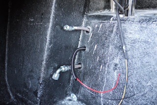
The other job I tackled recently was to drill the holes and pass the fuel lines and fuel pump wiring from under the rear of the car into the boot. I used some stepped grommets I got from Car Builder Solutions which took a bit of fitting as I didn't want to remove the fuel line end fittings so had to stretch the grommets over the end of them. After a bit of wrangling everything fell into place. I will probably need to secure the lines under the car to stop them rubbing on the chassis but I'll wait until the connections are tightened onto the tank before looking at this.



Fuel Tank
Had a bit of a break from the build just recently but with Xmas and the New Year out of the way I decided to tackle the fuel tank.
The first job was to mount the fuel sender. It comes as a kit and you have to adjust the length of the float arm to suit. Because the tank is divided in three sections to accomodate the internal baffles, in the section where the fuel sender sits, it's actually taller than it is long/wide so that to adjust it to read "empty" correctly, i.e with the float on the bottom of the tank, it's hits the side on the way up as it travels through an arc and will never reach the point at which it should read "full". I made a few measurements and in the end judged it by eye to be as long as possible at the full position i.e. horizontal, without touching the sides. This meant placing the float arm diagonally across the section and by positioning the float to be vertical and pointing down I figured I'd get more measurement at the bottom end when nearing empty, and sacrifice a little at the top end when the tank is full, or nearly full when the exact level is less critical. It was then a case of soldering the sender to its final length and fitting it to the tank.

This required 6 holes to be drilled around the sender opening and I opted to tap threads into the holes rather than use rivnuts.

I shamelessly stole and then developed an idea from another blog site and rather than use a muffin cup (thanks Steve) to catch the swarf inside the tank as I drilled, I used a cocktail umbrella. This was placed upside down through the opening and opened inside the tank thus catching the swarf from firstly the drilling and then the tapping of the sender fixing holes.

Seemed to work too !

It was then a case of tightning it all down with some stainless M5 buttom heads and fibre washers onto the supplied cork gasket smeared with blue hylomar gasket sealant.

The electrical connections will need a little fettling with the plastic cups cutting back and the spade connectors bending over to reduce the height and prevent fouling with other areas of the boot floor.
The first job was to mount the fuel sender. It comes as a kit and you have to adjust the length of the float arm to suit. Because the tank is divided in three sections to accomodate the internal baffles, in the section where the fuel sender sits, it's actually taller than it is long/wide so that to adjust it to read "empty" correctly, i.e with the float on the bottom of the tank, it's hits the side on the way up as it travels through an arc and will never reach the point at which it should read "full". I made a few measurements and in the end judged it by eye to be as long as possible at the full position i.e. horizontal, without touching the sides. This meant placing the float arm diagonally across the section and by positioning the float to be vertical and pointing down I figured I'd get more measurement at the bottom end when nearing empty, and sacrifice a little at the top end when the tank is full, or nearly full when the exact level is less critical. It was then a case of soldering the sender to its final length and fitting it to the tank.

This required 6 holes to be drilled around the sender opening and I opted to tap threads into the holes rather than use rivnuts.

I shamelessly stole and then developed an idea from another blog site and rather than use a muffin cup (thanks Steve) to catch the swarf inside the tank as I drilled, I used a cocktail umbrella. This was placed upside down through the opening and opened inside the tank thus catching the swarf from firstly the drilling and then the tapping of the sender fixing holes.

Seemed to work too !

It was then a case of tightning it all down with some stainless M5 buttom heads and fibre washers onto the supplied cork gasket smeared with blue hylomar gasket sealant.

The electrical connections will need a little fettling with the plastic cups cutting back and the spade connectors bending over to reduce the height and prevent fouling with other areas of the boot floor.
Sunday, 20 November 2011
Polishing
Because I'm working in a single garage and a little bit tight for space, I have for some time been moving the bonnet around the garage placing it on the body when I wasn't working on the car and leaning it up against as wall when I was. I was starting to get cheesed off with this so made an effort to get this part of the build finished. First I installed the resevoirs for the brakes, clutch and washer bottle.

I painted up the hinges with POR-15 which dries to a nice shiny and seemingly bullet proof finish but I did have a little trouble getting a nice clean appearance. The paint seemed quite thick and didn't flow as I would have liked. I may revisit these later and have them powder coated but for now they'll do. I don't get much time in the garage these days, I've come to realisation that if I go for perfection, I'll never get this thing finished. The next step was to polish the bonnet, well the middle section at least so I could bolt the scoop on permanently. Here's when things started to go downhill and my aim for perfection got in the way. I followed advice I got elsewhere and polished the bonnet with Farecla Profile 200 and a wool mop followed my Profile 500 and a lambswool mop.... result, shiny but scratched to hell :-( I was obviously doing something wrong. I set about masking the bonnet into different sections and using different combinations of compound and pads ( I have a few different ones that I've previously used on my tin top) to see which produced the best result. Not happy, I turned to the internet and after a little research bought some different compound and pads, and then some more after that. This seemed like the longest week ever with nothing seeming to work and being unable to attain anything like the finish I've seen and admired on other similar builds.
I finally gave up on the bonnet and moved onto a different area, partly to take my mind off the disastrous attempt at polishing the bonnet but I also wanted to get the windscreen fitted for the final time so set to work polishing the scuttle area. Given all the combinations of compounds and pads I'd tried I was determined to get it right. It seems someone was watching and as if by magic, it all came together.

And just to prove to myself it wasn't just luck I had another go at the bonnet

Sure there's still a few marks which I may go back with my newfound knowledge and experience and rectify but for now, that'll do for me !

I painted up the hinges with POR-15 which dries to a nice shiny and seemingly bullet proof finish but I did have a little trouble getting a nice clean appearance. The paint seemed quite thick and didn't flow as I would have liked. I may revisit these later and have them powder coated but for now they'll do. I don't get much time in the garage these days, I've come to realisation that if I go for perfection, I'll never get this thing finished. The next step was to polish the bonnet, well the middle section at least so I could bolt the scoop on permanently. Here's when things started to go downhill and my aim for perfection got in the way. I followed advice I got elsewhere and polished the bonnet with Farecla Profile 200 and a wool mop followed my Profile 500 and a lambswool mop.... result, shiny but scratched to hell :-( I was obviously doing something wrong. I set about masking the bonnet into different sections and using different combinations of compound and pads ( I have a few different ones that I've previously used on my tin top) to see which produced the best result. Not happy, I turned to the internet and after a little research bought some different compound and pads, and then some more after that. This seemed like the longest week ever with nothing seeming to work and being unable to attain anything like the finish I've seen and admired on other similar builds.
I finally gave up on the bonnet and moved onto a different area, partly to take my mind off the disastrous attempt at polishing the bonnet but I also wanted to get the windscreen fitted for the final time so set to work polishing the scuttle area. Given all the combinations of compounds and pads I'd tried I was determined to get it right. It seems someone was watching and as if by magic, it all came together.

And just to prove to myself it wasn't just luck I had another go at the bonnet

Sure there's still a few marks which I may go back with my newfound knowledge and experience and rectify but for now, that'll do for me !
Bit more work on the dash
I think I mentioned in an earlier post that my dash blank, being one of the first from GD (that seems like a long time ago) wasn't marked out with the gauge position so I had to do it myself. I borrowed a layout originally set up by Simon R which seems to have found its way around the web and marked the positions onto the blank before cutting out with a combination of the trusty Dremel with a radius cutter for the two large gauges and a holesaw for the smaller ones. Here's a before picture.

This was all part of a plan to mock up the dash so I could get an idea of where to mount the ECU, relays's etc that from part of the engine loom and need to be concealed behind the dash.
I also fitted the brace bar, which fits across the width of the car and bolts through the windscreen legs, and the dash support bar. This enables the under dash plates to be fitted into place.

The back edge of the plates is bolted onto the brace bar by drilling and tapping it, I used m5 with button head bolts. The front edge is simply wedged between the support bar and the bottom edge of the dash which has a right angled return but because I wanted to work with the dash plates and needed them to be held a little more firmly without relying on the dash to hold them in place, I made up a couple of brackets from some angle iron and welded them onto the support bar so they could be bolted at the front aswell. I used some m5 rivnuts for this.

Here's a picture with the bracket in place prior to welding which I wouldn't win any prizes for, but it does the job

The dash blank held in place with the support bars and under dash plates fitted. The dash itself is held in place along the top edge by some m4 button heads which pass through the lip on the underside of the scuttle and tightened from the back with some wingnuts. The button heads are self tapped into a 3.2mm hole and held firm with some araldite.


This was all part of a plan to mock up the dash so I could get an idea of where to mount the ECU, relays's etc that from part of the engine loom and need to be concealed behind the dash.
I also fitted the brace bar, which fits across the width of the car and bolts through the windscreen legs, and the dash support bar. This enables the under dash plates to be fitted into place.

The back edge of the plates is bolted onto the brace bar by drilling and tapping it, I used m5 with button head bolts. The front edge is simply wedged between the support bar and the bottom edge of the dash which has a right angled return but because I wanted to work with the dash plates and needed them to be held a little more firmly without relying on the dash to hold them in place, I made up a couple of brackets from some angle iron and welded them onto the support bar so they could be bolted at the front aswell. I used some m5 rivnuts for this.

Here's a picture with the bracket in place prior to welding which I wouldn't win any prizes for, but it does the job

The dash blank held in place with the support bars and under dash plates fitted. The dash itself is held in place along the top edge by some m4 button heads which pass through the lip on the underside of the scuttle and tightened from the back with some wingnuts. The button heads are self tapped into a 3.2mm hole and held firm with some araldite.

Sunday, 18 September 2011
Roll Bars Revisited
After the dust had settled I went back and had another look at the roll bars. In fairness, the holes weren't too far out but they did need a little bit of work. I've narrowed the problems I had down to two reasons.
1. The first set of bars fitted fine but for the second, it wasn't obvious which way the holes needed enlarging when they wouldn't initially fit. They appeared to be tight against the bodywork but in reality there were simply leaning forwards because of the third leg hanging into the cockpit. If I'd had the chassis level I could have checked the vertical.
2. I hadn't taken account of the flex required in the third leg, I allowed for the main legs but cut the rear hole to fit the bars in their unflexed state. Once flexed to fit the mounting points, the hole had been enlarged in the wrong direction.
I didn't take pictures of every step in the repair but with the few I have and a desription, hopefully you'll be able to follow what I did.
The first thing I did was to tape a piece of 1mm rubber mat around the roll bar where it passed through the body. I then cut a curve into a square of grp matting and glassed it in on the underside of the rear deck, up to the rubber mat wrapped around the roll bar. The rubber mat was to protect the roll bar and once removed, to give me some clearance to remove the roll bar afterwards.

When it had set, I filled the gap I'd created with Isopon p40 filler and then when that had set, removed the rubber mat and then the roll bar itself leaving a new fillet of grp filling the space which I had previously over enlarged.

Now because I had filled up to the roll bar itself, the repair was too much and needed cutting back to give the required clearance of 5mm all the way round.
Prior to making this repair I had cut two doughnuts out of a 1mm rubber sheet, both with the same outside diameter but one which had the same inside diameter as the roll bar and the second with the diameter that the hole needed to be, including the 5mm clearance. With the roll bar in position I placed the first doughnut around the roll bar and marked the outside circumference. With the roll bar removed, I placed the second doughnut into position, carefully lining up the outside circumference with the marks made for the previous doughnut. I now had a reference point to enlarge the hole, along with the repair, to give the neccessary clearance.

Once the hole had been enlarged to match the inside circumference of the second doughnut, the filler was also cut back on it's surface ready for gel coat to be applied.

Once the gel had gone off, it was rubbed down level to the bodywork and repolished before the roll bars were refitted to see if it had all been a success...

There may still be a little fettling required but it looks good to me and with the grommet fitted, nobody would ever know...!

A couple of gratuitous shots to show how it's looking.


1. The first set of bars fitted fine but for the second, it wasn't obvious which way the holes needed enlarging when they wouldn't initially fit. They appeared to be tight against the bodywork but in reality there were simply leaning forwards because of the third leg hanging into the cockpit. If I'd had the chassis level I could have checked the vertical.
2. I hadn't taken account of the flex required in the third leg, I allowed for the main legs but cut the rear hole to fit the bars in their unflexed state. Once flexed to fit the mounting points, the hole had been enlarged in the wrong direction.
I didn't take pictures of every step in the repair but with the few I have and a desription, hopefully you'll be able to follow what I did.
The first thing I did was to tape a piece of 1mm rubber mat around the roll bar where it passed through the body. I then cut a curve into a square of grp matting and glassed it in on the underside of the rear deck, up to the rubber mat wrapped around the roll bar. The rubber mat was to protect the roll bar and once removed, to give me some clearance to remove the roll bar afterwards.

When it had set, I filled the gap I'd created with Isopon p40 filler and then when that had set, removed the rubber mat and then the roll bar itself leaving a new fillet of grp filling the space which I had previously over enlarged.

Now because I had filled up to the roll bar itself, the repair was too much and needed cutting back to give the required clearance of 5mm all the way round.
Prior to making this repair I had cut two doughnuts out of a 1mm rubber sheet, both with the same outside diameter but one which had the same inside diameter as the roll bar and the second with the diameter that the hole needed to be, including the 5mm clearance. With the roll bar in position I placed the first doughnut around the roll bar and marked the outside circumference. With the roll bar removed, I placed the second doughnut into position, carefully lining up the outside circumference with the marks made for the previous doughnut. I now had a reference point to enlarge the hole, along with the repair, to give the neccessary clearance.

Once the hole had been enlarged to match the inside circumference of the second doughnut, the filler was also cut back on it's surface ready for gel coat to be applied.
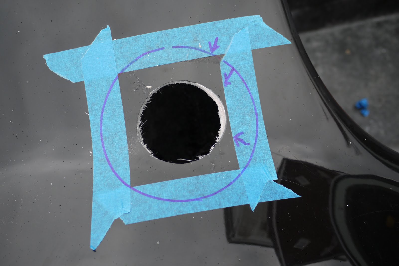
Once the gel had gone off, it was rubbed down level to the bodywork and repolished before the roll bars were refitted to see if it had all been a success...

There may still be a little fettling required but it looks good to me and with the grommet fitted, nobody would ever know...!

A couple of gratuitous shots to show how it's looking.


Sunday, 11 September 2011
Better Pictures...
Because of the poor weather we've had, most of the recent pictures have been taken in the garage and weren't particularly good. As well as promising myself to learn how to use my camera properly, I also vowed to take some pictures outside as soon as the weather cleared, so here they are... other than temporarily fitting the air intake, no further progress, just better pictures :-)


Two things before I go, firstly a quick hello to my old friend Casey and secondly, if you want to see what this build has been all about, you have to stop by Steve's pages (link on the right hand side) and check out the fun he had at a recent trackday. Direct link here
Don't forget to watch the video's, fantastic stuff.


Two things before I go, firstly a quick hello to my old friend Casey and secondly, if you want to see what this build has been all about, you have to stop by Steve's pages (link on the right hand side) and check out the fun he had at a recent trackday. Direct link here
Don't forget to watch the video's, fantastic stuff.
Subscribe to:
Posts (Atom)