
GD427 in action

Wednesday, 12 May 2010
Bit of fun...
As well as finishing off a few loose ends around the body today, I built this... supposedly for the kids but I want first go !


Tidying up..
Had another good day today, not much to show for it but basically went round and tidied up a few loose ends. Finished the extended footwell, polished the engine bay in readiness to fit the forward wiring loom and finished off a few rough edges underneath that were left over from when the body was in the mould.


Tuesday, 11 May 2010
Pedal Box & Extended Footwell
Managed to get a bit more done today namely fitting the pedal box and the extended footwell. I actually made the cut for the extended footwell some time ago and all I really did today was drill the mounting holes and fit the jacknuts to hold it in place. It still needs a little fettling to get everything lined up and them some additional bodywork cut away to open the hole up as I deliberately cut it too small to start with. You can always make a small hole bigger...


I started the pedal box by removing the pedals and roughly positioning the frame to get an idea where it should go. The frame is mounted as far left as possible leaving enough room to fit the carpet alongside. The top of the frame sits roughly 5mm below the curved ledge that is the horizontal corner section in the engine bay. By marking and drilling the centre hole first, you can temporarily fit the frame in place which makes it much easier to mark the other holes. 


I started the pedal box by removing the pedals and roughly positioning the frame to get an idea where it should go. The frame is mounted as far left as possible leaving enough room to fit the carpet alongside. The top of the frame sits roughly 5mm below the curved ledge that is the horizontal corner section in the engine bay. By marking and drilling the centre hole first, you can temporarily fit the frame in place which makes it much easier to mark the other holes.


Access Panels to Footwell Compartments
With hindsight, I'm probably better using standard M5 bolts than button heads to secure the access panels. With all the rubbish thrown up under the wheel arches once on the road, bolts with a standard hex head will be a lot easier to remove using a socket/spanner than button heads with an Allen key. I'll add some bolts to my shopping list and change them over at a later date.
I've also chosen to secure the panels at the corners, it's crossed my mind whether these would have been better secured half way along the edges to pull the panel tighter against the bulkhead, I guess time will tell...
I've also chosen to secure the panels at the corners, it's crossed my mind whether these would have been better secured half way along the edges to pull the panel tighter against the bulkhead, I guess time will tell...
Monday, 10 May 2010
A Step Closer...
A bit more progress made, no big write up, all fairly self explanatory
Front lights & Indicators fitted


Rear wiring loom fitted


Access panels fitted to footwell compartments. These were backed with strips of 2mm neoprene and fitted with M5 button heads into jacknuts.


Front lights & Indicators fitted


Rear wiring loom fitted


Access panels fitted to footwell compartments. These were backed with strips of 2mm neoprene and fitted with M5 button heads into jacknuts.


The grey strip you can see on the outside edge of the wheel arches is a piece of foam pipe lagging that I've used to protect the edges when I'm pushing the body in and out of the garage.
Monday, 12 April 2010
Fitting The Bonnet
After a long break from the garage, (I think I may be a "fair weather" builder !) I found some time over the weekend to pick up the tools and make some more progress on the build. My last major accomplishment was fitting the bootlid and with the same approach in mind I set about fitting the bonnet.

Using small strips of card I "gapped" the bonnet by sitting it in the opening and wedging pieces of card along the sides to centralise it. Once centred I measured the drop in height between the bonnet and the surround and made some spacers, again out of pieces of card to sit in the aperture and raise the bonnet to the correct height. After a few last minute tweeks I attached the bonnet hinges to the body through the radiator opening and swung the hinges up to meet the underside of the bonnet to gauge how much fettling would be required to get them to fit. Unfortunately, quite a bit... I decided that the best approach would be to re-weld the hinge plates to the arms and set about cutting them off.

Once removed I fitted the plates to the bonnet and the hinge arms to the body, I then swung the arms up to meet the plates and held them in place with a few tack welds. Once it had cooled down, I removed the hinge, made a permanent job of the welds on the bench and re-fitted.

Voila, perfectly fitted hinges with a perfectly centred and height adjusted bonnet


Using small strips of card I "gapped" the bonnet by sitting it in the opening and wedging pieces of card along the sides to centralise it. Once centred I measured the drop in height between the bonnet and the surround and made some spacers, again out of pieces of card to sit in the aperture and raise the bonnet to the correct height. After a few last minute tweeks I attached the bonnet hinges to the body through the radiator opening and swung the hinges up to meet the underside of the bonnet to gauge how much fettling would be required to get them to fit. Unfortunately, quite a bit... I decided that the best approach would be to re-weld the hinge plates to the arms and set about cutting them off.

Once removed I fitted the plates to the bonnet and the hinge arms to the body, I then swung the arms up to meet the plates and held them in place with a few tack welds. Once it had cooled down, I removed the hinge, made a permanent job of the welds on the bench and re-fitted.

Voila, perfectly fitted hinges with a perfectly centred and height adjusted bonnet

Saturday, 7 November 2009
Boot Lid Pictures
I spent a fair bit of time positioning this catch in the middle of the boot opening only to find it didn't line up with the locking mechanism and handle which was positioned in the middle of the boot lid. I guess I was expecting too much, alternatively, I didn't think it through properly.... you choose. As it's more important for the handle to be in the centre of the boot lid I had to move the catch across a little to line up.

The boot lid was positioned by packing the opening with card held down by masking tape to bring it up to the correct height and to hold it central. In this way I could remove and replace the boot lid to my hearts content knowing that it went back in the same position each time.

With some help from my Dad... hey Dad, you're on the internet !... I climbed into the boot and had my Dad replace the bootlid behind me. I could then bolt the hinges into place and offer up the boot catch to mark it's position before fixing.

Here's the catch after fitting the T-Handle on the outside of the boot lid. The square section will be cut to length later.

I also took the opportunity to fit the rear lights, indicators and number plate light. Another step closer and looking a bit more like a car.
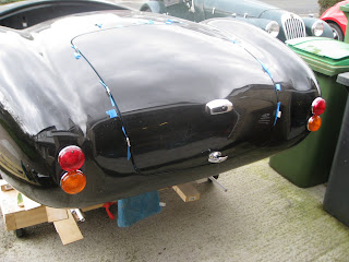

The boot lid was positioned by packing the opening with card held down by masking tape to bring it up to the correct height and to hold it central. In this way I could remove and replace the boot lid to my hearts content knowing that it went back in the same position each time.

With some help from my Dad... hey Dad, you're on the internet !... I climbed into the boot and had my Dad replace the bootlid behind me. I could then bolt the hinges into place and offer up the boot catch to mark it's position before fixing.

Here's the catch after fitting the T-Handle on the outside of the boot lid. The square section will be cut to length later.

I also took the opportunity to fit the rear lights, indicators and number plate light. Another step closer and looking a bit more like a car.

Subscribe to:
Posts (Atom)