With hindsight, I'm probably better using standard M5 bolts than button heads to secure the access panels. With all the rubbish thrown up under the wheel arches once on the road, bolts with a standard hex head will be a lot easier to remove using a socket/spanner than button heads with an Allen key. I'll add some bolts to my shopping list and change them over at a later date.
I've also chosen to secure the panels at the corners, it's crossed my mind whether these would have been better secured half way along the edges to pull the panel tighter against the bulkhead, I guess time will tell...
GD427 in action

Tuesday, 11 May 2010

Monday, 10 May 2010
A Step Closer...
A bit more progress made, no big write up, all fairly self explanatory
Front lights & Indicators fitted


Rear wiring loom fitted


Access panels fitted to footwell compartments. These were backed with strips of 2mm neoprene and fitted with M5 button heads into jacknuts.


Front lights & Indicators fitted


Rear wiring loom fitted


Access panels fitted to footwell compartments. These were backed with strips of 2mm neoprene and fitted with M5 button heads into jacknuts.


The grey strip you can see on the outside edge of the wheel arches is a piece of foam pipe lagging that I've used to protect the edges when I'm pushing the body in and out of the garage.
Monday, 12 April 2010
Fitting The Bonnet
After a long break from the garage, (I think I may be a "fair weather" builder !) I found some time over the weekend to pick up the tools and make some more progress on the build. My last major accomplishment was fitting the bootlid and with the same approach in mind I set about fitting the bonnet.

Using small strips of card I "gapped" the bonnet by sitting it in the opening and wedging pieces of card along the sides to centralise it. Once centred I measured the drop in height between the bonnet and the surround and made some spacers, again out of pieces of card to sit in the aperture and raise the bonnet to the correct height. After a few last minute tweeks I attached the bonnet hinges to the body through the radiator opening and swung the hinges up to meet the underside of the bonnet to gauge how much fettling would be required to get them to fit. Unfortunately, quite a bit... I decided that the best approach would be to re-weld the hinge plates to the arms and set about cutting them off.

Once removed I fitted the plates to the bonnet and the hinge arms to the body, I then swung the arms up to meet the plates and held them in place with a few tack welds. Once it had cooled down, I removed the hinge, made a permanent job of the welds on the bench and re-fitted.

Voila, perfectly fitted hinges with a perfectly centred and height adjusted bonnet


Using small strips of card I "gapped" the bonnet by sitting it in the opening and wedging pieces of card along the sides to centralise it. Once centred I measured the drop in height between the bonnet and the surround and made some spacers, again out of pieces of card to sit in the aperture and raise the bonnet to the correct height. After a few last minute tweeks I attached the bonnet hinges to the body through the radiator opening and swung the hinges up to meet the underside of the bonnet to gauge how much fettling would be required to get them to fit. Unfortunately, quite a bit... I decided that the best approach would be to re-weld the hinge plates to the arms and set about cutting them off.

Once removed I fitted the plates to the bonnet and the hinge arms to the body, I then swung the arms up to meet the plates and held them in place with a few tack welds. Once it had cooled down, I removed the hinge, made a permanent job of the welds on the bench and re-fitted.

Voila, perfectly fitted hinges with a perfectly centred and height adjusted bonnet

Saturday, 7 November 2009
Boot Lid Pictures
I spent a fair bit of time positioning this catch in the middle of the boot opening only to find it didn't line up with the locking mechanism and handle which was positioned in the middle of the boot lid. I guess I was expecting too much, alternatively, I didn't think it through properly.... you choose. As it's more important for the handle to be in the centre of the boot lid I had to move the catch across a little to line up.

The boot lid was positioned by packing the opening with card held down by masking tape to bring it up to the correct height and to hold it central. In this way I could remove and replace the boot lid to my hearts content knowing that it went back in the same position each time.

With some help from my Dad... hey Dad, you're on the internet !... I climbed into the boot and had my Dad replace the bootlid behind me. I could then bolt the hinges into place and offer up the boot catch to mark it's position before fixing.

Here's the catch after fitting the T-Handle on the outside of the boot lid. The square section will be cut to length later.

I also took the opportunity to fit the rear lights, indicators and number plate light. Another step closer and looking a bit more like a car.
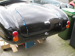

The boot lid was positioned by packing the opening with card held down by masking tape to bring it up to the correct height and to hold it central. In this way I could remove and replace the boot lid to my hearts content knowing that it went back in the same position each time.

With some help from my Dad... hey Dad, you're on the internet !... I climbed into the boot and had my Dad replace the bootlid behind me. I could then bolt the hinges into place and offer up the boot catch to mark it's position before fixing.

Here's the catch after fitting the T-Handle on the outside of the boot lid. The square section will be cut to length later.

I also took the opportunity to fit the rear lights, indicators and number plate light. Another step closer and looking a bit more like a car.

Sunday, 25 October 2009
Fitting the boot lid
Camera's playing up at the moment so I can't upload any pictures but I'll update this post as soon as normal service resumes. I've not posted for a while, I have been making some progress but since the small issue with the petrol filler, I've been a little more cautious. In addition, I've decided at the ripe old age of 41 to get me some "ejucation" and I've picked up the text book once more to work towards a professional qualification in Insurance and as my employer has a nice little bonus scheme for passing these exams I thought I'd give it a go.
The latest job to be completed on the car was fitting the bootlid which is held in place by two hinges on the front edge and the lock at the back. The bootlid needs aligned to be central in the boot aperture both front to back and side to side. In addition it's height needs to be the same or at least as close as possible to the surrounding body work. The standard method involves a lot of trial and error and either bending or packing the hinges to achieve the desired result. In order to find out just how much faffing about I was in for I decided to fit the lid in the correct position, held in place by card and masking tape to see how far out the hinges would be. I packed the edge of the aperture with thin strips of card to raise the lid to the correct height and then wedged card into the shut lines to hold it central. Once I was happy, I taped all the card into place, fitted the hinges to the body and with my Dad's help, climbed into the boot and closed the lid behind me. I could then lift the hinges into place against the inside of the bootlid to see how much work was needed to get a good fit. Happily, the hinge plates fitted flush against the underside of the lid showing that just a few of the holes needed enlarging for it all to line up and bolt into place. Nice!
The next job was to fit the catch which is fitted or at least marked for fitment from inside the boot. I'd previously spent a good while positioning the striker plate in the exact centre of the aperture before fixing into place. I fitted the catch to align with the striker plate but it wasn't until I came to fit the handle to the outside of boot lid that I realised that the critical measurement was the handle in the centre of the lid rather than the catch/striker in the centre of the aperture and mine was a little out. I managed to "save" it but there's a good tip for anyone else contemplating the same job. I'll try and post a few pictures to illustrate but I've now fitted the bootlid, fitted the boot handle and lock, the number plate light and the rear lights and indicators. A couple of small jobs in the great scheme of things but the back end now looks like a car which gives a very satisfying feeling. Oh whilst I think of it, another small tip for you, the hole cut for the fuel filler makes a handy hole to feed a lead light through so you can have some light and see what you're doing when you climb into the boot.
The latest job to be completed on the car was fitting the bootlid which is held in place by two hinges on the front edge and the lock at the back. The bootlid needs aligned to be central in the boot aperture both front to back and side to side. In addition it's height needs to be the same or at least as close as possible to the surrounding body work. The standard method involves a lot of trial and error and either bending or packing the hinges to achieve the desired result. In order to find out just how much faffing about I was in for I decided to fit the lid in the correct position, held in place by card and masking tape to see how far out the hinges would be. I packed the edge of the aperture with thin strips of card to raise the lid to the correct height and then wedged card into the shut lines to hold it central. Once I was happy, I taped all the card into place, fitted the hinges to the body and with my Dad's help, climbed into the boot and closed the lid behind me. I could then lift the hinges into place against the inside of the bootlid to see how much work was needed to get a good fit. Happily, the hinge plates fitted flush against the underside of the lid showing that just a few of the holes needed enlarging for it all to line up and bolt into place. Nice!
The next job was to fit the catch which is fitted or at least marked for fitment from inside the boot. I'd previously spent a good while positioning the striker plate in the exact centre of the aperture before fixing into place. I fitted the catch to align with the striker plate but it wasn't until I came to fit the handle to the outside of boot lid that I realised that the critical measurement was the handle in the centre of the lid rather than the catch/striker in the centre of the aperture and mine was a little out. I managed to "save" it but there's a good tip for anyone else contemplating the same job. I'll try and post a few pictures to illustrate but I've now fitted the bootlid, fitted the boot handle and lock, the number plate light and the rear lights and indicators. A couple of small jobs in the great scheme of things but the back end now looks like a car which gives a very satisfying feeling. Oh whilst I think of it, another small tip for you, the hole cut for the fuel filler makes a handy hole to feed a lead light through so you can have some light and see what you're doing when you climb into the boot.
Friday, 25 September 2009
Fuel Filler Cap
GD had very kindly, clearly marked onto the body the position and exact size of the hole needed to mount the fuel filler. I then, very clearly, drilled the hole too big. Entirely my fault, working late into the evening, getting a bit carried away and just used the wrong size hole saw. Used a 76mm hole saw when I should have used a 64mm.

Now, you can always make a small hole bigger but making a big hole smaller poses a few issues. I guess there a few ways I could've tackled this, I understand there is a filler cap with a larger flange which would've covered the mistake but it looked a bit ugly to me and cost about £80. I could've made a collar to fit inside the hole and reduce the inside diameter but how would I fix it in place. An additional challenge faced me in that when I measured the fuel filler in the hole, the fixing bolt holes were directly in line with any repair I attempted to make meaning that whatever solution I chose it had to be strong and solidly fixed to the body. In the end I chose to re-affix the part I had drilled out which was still lodged inside the holesaw after I abandoned it in digust onto the workbench. Luckily there were enough marks left on it from the original masking tape that I could use as a guide to position the piece precisely where it had come from. I then used additional masking tape and drew some guideline upon it to ensure I had it positioned correctly before suspending the part in it's orginal position using a couple of battens and using a fibreglass kit to place a strip either side and glass the piece back into position from the underside.


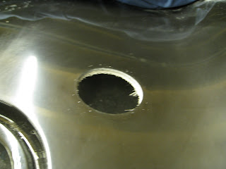


Now, you can always make a small hole bigger but making a big hole smaller poses a few issues. I guess there a few ways I could've tackled this, I understand there is a filler cap with a larger flange which would've covered the mistake but it looked a bit ugly to me and cost about £80. I could've made a collar to fit inside the hole and reduce the inside diameter but how would I fix it in place. An additional challenge faced me in that when I measured the fuel filler in the hole, the fixing bolt holes were directly in line with any repair I attempted to make meaning that whatever solution I chose it had to be strong and solidly fixed to the body. In the end I chose to re-affix the part I had drilled out which was still lodged inside the holesaw after I abandoned it in digust onto the workbench. Luckily there were enough marks left on it from the original masking tape that I could use as a guide to position the piece precisely where it had come from. I then used additional masking tape and drew some guideline upon it to ensure I had it positioned correctly before suspending the part in it's orginal position using a couple of battens and using a fibreglass kit to place a strip either side and glass the piece back into position from the underside.


Once the initial repair was dry, I removed the batten, placed a strip of fibreglass in the middle and then two extra pieces which covered the whole area.

I then filled the hole which was left by the original holesaw cut with some fibreglass filler before cutting back with the trusty Dremmel and filling with gelcoat and sanding back with wet n dry.


I was quite pleased with the end result and whilst perhaps not as good as it could have been, it was far better than it needed to be considering it would all be covered by the flange on the fuel filler anyway. The hole was drilled once more, this time with the correct size holesaw and finally, as a belt and braces job, I made a plate from 2mm aluminium to fit on the underside of the body for the fixing bolts to pass through and strengthen the whole thing up, effectively clamping the repair between the plate and the filler itself. I will need to get some longer bolts to pass through the extra thickness of the body.


Whilst I would never have chosen to follow this path, I did quite enjoy myself and learnt a little about fibreglassing along the way.... can you tell I'm still trying to put a brave face on....sob, sob !
A new section
Not posted for a little while. A few reasons, been busy working on the house, been busy at work, been ill with the worst bought of flu imagineable (for me anyway) and the recent work completed on the car hasn't really gone to plan....hence a new section to the site.... cock ups. Hopefully thee won't be too many posts :-)
Subscribe to:
Posts (Atom)